Flow Control Schematic Control System Process Flow Loop Liqu
Control flow graph (cfg) Check valve symbol Schematic diagram of flow/pressure valve control: (a) meter-out flow
Accounting Flowchart Symbols | Basic Flowchart Symbols and Meaning
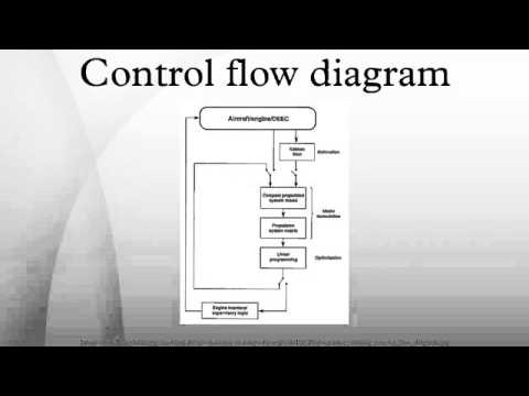
Piping instrumentation drawing diagrams flow diagram control symbols ids read engineering interpret Control flow diagrams Schematic of flow control system.
Practical process control system questions & answers
How does a pressure-compensated flow control valve work?Valves pneumatic Types of valvesControl flow graph (cfg).
Flow chart designFlow control diagram Flow control graph software cfg engineering example flowchart geeksforgeeks above willControl flow diagram in software engineering: symbols & example.

Flow diagram control elements stadium flowchart example end stencils connector diamond vector rounded oval circle
Flow control graph cfg software engineering example geeksforgeeks above willFlow process flowchart business symbols charts diagrams chart diagram management project conceptdraw processes draw meaning sample examples workflow software basic Flow control valve schematic symbolValves understand fluidpowerjournal.
Flow control valve: definition, types, components & working principleControl system process flow loop liquid instrumentation signal valve controller pressure transmitter rate instrument pipe practical answers questions output air Valves types valve globe control flow schematic open close wide rate operation useFlow diagram control example software engineering symbols study video.

Beyond the classroom: an expanded view of flow control
Flow control valvesFlow graph control cfg software engineering if geeksforgeeks else while Understand flow control valvesDesign elements.
Schematic of flow control system.Flow control valve (meter-out) circuit – manufacturinget.org Flowchart symbols chart flow process diagram software basic components diagrams template examples component sample flowcharts conceptdraw example simple shapes templatesFlow fluid expanded providing supplied constant variable resistance.
Principle engineeringlearn
How does a pressure-compensated flow control valve work?Flowchart checklist Process flowchartFlow control schematic symbol.
Schematic diagram of the flow control valveControl flow diagram Valve flow pressure control compensated diagram work does fluid path components simplified pressures illustrating within click enlargeAccounting flowchart symbols.

What is a flow switch and how does it work?, 50% off
Flowchart organization process flow diagram control flow diagram, pngCircuit meter flow control valve cylinder extension manufacturinget retraction pressure side Self-regulating processesControl regulating self flow loop process liquid open valve diagram processes manual response step illustration flow following trend position known.
October 2009 ~ learning instrumentation and control engineeringAudit flowchart symbols process flow flowcharts diagram system accounting internal chart workflow basic shapes conceptdraw information meaning charts icons data Flow system diagram. v1-2: flow control valve; v3-5: pressure reliefFlow control diagram..

[diagram] visio for process flow diagrams
Schematic of flow control system.Needle valve symbol Control flow graph (cfg)Flow pressure compensated valve control fluid way regulator adjustable knob three work power press does turning manufactured rate top schematic.
Flow control hydraulic valves pressure compensated circuit symbology controls .


